 |
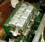
Lister SR3
A 3 cylinder air cooled diesel utility engine, popular for use in boats. Good british engineering, and a simple design makes it last for ever - well almost. After 40 years this one needs some work on it. Click on the image for where things are on it. |
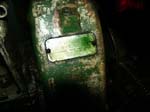 |
Engine Plate
Serial Number: 635SR314D A 1964 example - add 50 to the last two numbers. The D designation may mean this engine was not originally designed for a boat, but I do not know what it does mean! Phil Rushton tells me, M stands for Marine and G & R stand for gearbox and reduction gearbox respectively on his SR2 serial plate. A handy page for dating an engine is here,
|
|
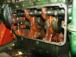
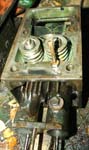
Inside view of the Crankcase
At the top of the image inside the engine is the camshaft, on which sit the pushrods, which in turn conenct to the valves. The crankshaft can be seen in the middle, with large counter balance weights to help with the thrust from the piston. Each conrod is connected to the crank at 120 degrees apart - as it's a three cylinder engine. At the right side of the crankcase panel (with the spring) is the oil pump which runs off the camshaft. |
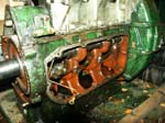 |
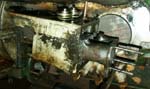
Port side of engine
View of the left hand side of the engine, with the crank case door removed. On the left of the picture is the cog that drives the camshaft. |
 |
Camshaft
In this side view you can see the camshaft near the top of the opening, and the push rods sitting on top of the sections with the lobes. Just visable is the Crankshaft at the bottom. |
 |
Fuel Pump Housing
This is where the fuel/injector pump sits - one for each cylinder. |
 |
View of the crankshaft
This is a top down view of the crankshaft. The starter motor would be at the top of the picture if it had not been removed! |
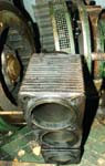 |
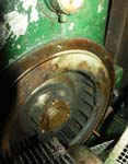
Air fan, and Cylinder block
On the left of the picture is the back end of the engine, showing the flywheel, with fan blades which push the air around the engine for the cooling. At the back in the middle is the fan guard, and then attached is part of the gear box casing. At the front are the cylinder blocks, with vents to aid cooling. The tops of the cylinders are towards us, and you can see the scoring where the pistons run up and down further into the barrel. |
 |
Flywheel and oil gauge
Flywheel, and fan. At the top of the image just in shot is the oil presure gauge. The problem is that after time it fails, and could cause loss of oil pressure. Peter mentioned the pipe to the gauge should be blocked up to stop any problems - since I can not see the gauge normally anyway. |
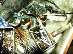 |
Parts of a Lister SR3
Most of the small bits out of my Lister SR3! The rods at the bottom are the valve push rods. In there should be three cylinders,three rocker covers, and in each cover is an injector pump. |
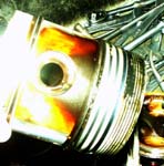 |
Piston
An over exposed image of the piston. The piston rings are clearly visable towards the right of the image. |
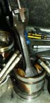 |
Piston, and Conrod
At the bottom of the image is the piston. You can see the piston rings (inset), which are worn. Connected to it is the 'Connector Rod', which joins the Piston to the Crankshaft. At the top of the assembly is the "rod bearing", a cup which sits on the crankshaft. |
 |
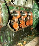
Cylinder Head Top View
The cyclinder head as viewed from the starboard (right) side. At the bottom is the Exhaust (left), and Air (right) ports. Note the cooling fins (especially on the exhaust), since air is used for cooling this engine. The pipe sticking up is a crankcase breather. It's a "bundy pipe", and one is screwed into the top of each cylinder on the engine, and connects with the inlet port. Vapour is drawn into the inlet manifold, and partial vacuum is maintained in the crank case which prevents oil leakage through the joints and bearings. The value springs are visable in the middle of the picture, and towards the rear is a large hole where the injector would sit. |
 |
Cylinder Head
TThe bit at the top of the engine which houses the valves. The springs seen at the top of the picture would normally be at the top of the engine under the rocker cover. This is a side view. |
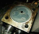 |
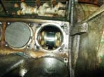
Cylinder Head
If this was in place, to get the same view you would be looking upwards from the piston. The valves can be seen clearly, and the hole in the middle is where the fuel injector sits. |
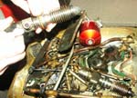 |
Injector
In Peter's hands is a diesel injector. The bit that goes into the cylinder is on the right hand side, hence the carbonisation. The yellow ring in his left hand is the injector oil seal ring. You can see either the Leak-off pipe, or fuel pipe inlet pointing towards the camera. I'm not sure, but I guess the cooling fins around it are to keep it cool from the explosions heating up the end. |
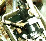 |
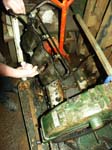
Fuel Pump
A close up of the Fuel Pump. On the left is the fuel pump linkage which controls the flow, and links all the pumps together. At the bottom right corner is where it rests on the camshaft rod, which provides the power for the pump. Inlet valve is the connector pointing towards the camera I think. |